Aerodynamic Design
Duct Aerodynamics
Wing Aerodynamics
The Wing/Duct Lifting System
Aileron Aerodynamics
Tail Surface Aerodynamics
Forward Fuselage Aerodynamics
Ventral Fin Aerodynamics
Static and Dynamic Stability
Wing Loading
A key element of the Hummingbird concept is to simultaneously reduce wing-loading and size over conventional aerobatic aircraft. While modern competition aircraft typically have wing-loadings of around 14 to 16 lb/sq ft, the goal for Hummingbird is an effective wing loading of 12 to 13 lb/sq ft, while keeping wing span under 20ft. To achieve this without encountering excessive induced drag penalties is possible because of two key features:
- Very high power-to-weight ratio engines and advanced structures, resulting in low aerobatic weights.
- The inherent span-efficiency of the wing/duct lifting system.
[Note: It has been suggested that a sub-20 foot span airplane is too small to be clearly seen and judged in competition. While Hummingbird certainly won’t look like an Extra or Sukhoi in the air, it will be relatively easy to see and judge due to the large overall surface area, symmetrical geometry (fuselage and empennage centered on duct axis), and straight trailing edges.]
Duct/Annular Wing Aerodynamics
The duct has three aerodynamic functions:
- Increase thrust at low and zero airspeeds.
- Provide aerodynamic lift at all lateral attitudes.
- Aerodynamically couple the lifting system and propulsion system.
The duct's effectiveness for each function will increase with duct diameter. The aircraft’s configuration forces a practical limit on duct diameter of around 90 inches. Duct chord is minimized to create an annular wing of reasonable L/D, but turns out to be limited by propeller clearance and structural issues (presently 35.5 inches).
The duct airfoil section is being developed with consideration for propulsive, L/D, stall, and blade clearance requirements. Leading edge radius is large to discourage inlet separation under static conditions. Structural considerations encourage the use of a relatively thick duct airfoil—presently 18% t/c. A relatively thick airfoil also appears to offer the best aerodynamic tradeoffs. The duct inner airfoil surface is also constrained by the practical need to keep the duct surface as perpendicular as possible to the propeller blades, to avoid tip clearance closure with blade flexing.
With duct diameter and chord established (predominantly by practical constraints), the aerodynamic design of the duct can be simplified to reflect two major parameters: airfoil section and camber (inlet/outlet area). A slightly positive camber corresponds fortuitously with the need to delay the stall of the duct inside surface (thus maintaining propulsive efficiency) until after the aircraft is generally stalled. Duct diffuser geometry is driven by L/D and stall development, not by a requirement for optimum thrust.
It should be noted that propeller tip clearances will be greater than what would be optimum considering propulsive issues alone. Duct induced surface velocities will therefore be lower than propulsive optimums, which greatly relieves duct airfoil compromises driven by the need to prevent inlet separation under high power, static conditions.
Wing Aerodynamics
Since Hummingbird is designed to fly identically upright or inverted, all wing airfoil sections are symmetrical. For the same reason, the wing has no twist and no dihedral, and both wing and stabilizer are rigged at zero incidence. The airplane’s aerodynamic characteristics are tailored through airfoils and planforms alone.
Planform
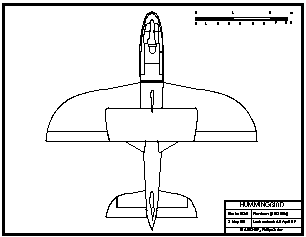
The depicted planform is essentially elliptical, swept so that the trailing edge is straight with zero sweep. This planform provides several advantages:
- Induced drag is minimized, since lift distribution is near optimum, and because the span efficiency of a planar wing is optimized when maximum span is at the trailing edge.
- Aileron power is maximized. This wing planform allows the greatest aileron span and area relative to wing area.
- The sweep moves the aerodynamic center of the wing closer to that of the duct, and the aerodynamic center of the entire configuration towards the correct location relative to the expected aircraft CG.
- Moderate sweep is generally found to enhance snap-roll and spin entry characteristics.
Note that the effective (aerodynamic) sweep will be less than the wing geometric sweep, due to the duct's contribution to the lift vortex.
A further virtue of this planform is the visual order created by the straight trailing edges of all flying surfaces (except the stators).
A simpler and more easily manufactured double-taper planform could probably be devised, with the risk of leading edge separation at the taper break at lateral angles of attack. Further, it must be noted that this is an exhibition airplane; visually, the complex planforms are considered well worth the extra effort. Also, since right and left wings are structurally and aerodynamically identical, and manufactured in the same tooling, the complex tooling need only be manufactured once.
Winglets
Small winglets may be utilized, mainly to increase pressures on the outboard aileron and thus improve roll rate. The winglets have a secondary role to reduce induced drag, which translates into reduced energy losses during high-G maneuvers. In order to function at both positive and negative G, the winglets will be symmetrical airfoils rigged at zero incidence and will need to be highly swept to cope with the widely varying flow conditions at the wing tip. Slight winglet toe-in or toe-out may be required to fine-tune snap performance.
It would be easy to overlook the use of winglets, since there is already more than enough vertical area on the airplane. But such an opportunity to increase roll rate, while simultaneously reducing adverse yaw and induced drag, cannot be ignored. It remains to be seen how winglets will affect stall and snap-roll behavior. The aircraft will probably be flight tested both with and without winglets before a decision is made on their utilization.
Stall characteristics
The stall characteristics of this planform are the subject of continuing study, both with and without winglets. The overall sweep and taper of the depicted wing will tend to move the stall outboard, while the raked tip will tend to delay the stall in that area. For good snap-roll performance, it is essential that, with crossed controls, an entire outboard wing can be made to stall simultaneously.
There will be interesting aerodynamic effects seen at the wing/duct intersection. As the aircraft is yawed, the pressures on the duct near the wing will influence the airflow over the wing, particularly as either the wing or the duct approaches the stall. The interaction of wing and duct in a stalled or semi-stalled condition, such as during a spin or snap-roll, is of particular interest.
Wing airfoils
The blended airfoil sections at the wing/duct intersection, of 11% and 25% t/c, have been the subject of intensive development. The current 11% section has excellent L/D, high CLmax, and a very deep stall break, with low drag at low lift coefficients (required to offset the large surface areas at high speeds). The 25% inboard section shows very low drag (resulting from significant laminar flow) up to moderate angles of attack. The design process of this inboard wing section is compounded by its interaction with the propulsion system at high angles of attack.
The 11% section forms the basis for the remaining outboard wing sections, which transform continuously over the semi-span due to the constant aft-spar thickness resulting from the constant-chord aileron geometry. Specialized software has been developed to perform these airfoil transformations.
The Wing/Duct Lifting System
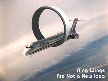
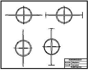
Hummingbird’s wing/duct lifting system combines many advantages of the biplane configuration with advantages of the monoplane, while avoiding some of their most significant compromises. A biplane gains its superior span-efficiency by distributing its work over a larger vertical mass of air; similarly, Hummingbird’s duct is working directly on a mass of air over a vertical extent of more than eight feet—at any angle of bank. Moreover, Hummingbird’s structural configuration is self-bracing, but without the drag-producing flying wires of the biplane.
Hummingbird’s duct accounts for about 35% of the total lift generated in level flight, and about 75% of the total lift during knife-edge flight. When one considers the theoretical fact that an annular lifting surface produces just half the induced drag of a planar wing of the same span producing the same lift, one can appreciate the superior efficiencies inherent in the wing/duct lifting system for aerobatic flight.
The tight integration of Hummingbird’s lifting system and propulsion system will provide unique “powered lift” effects at slow speeds. This is a result of a significant portion of the inboard lifting system being immersed in the accelerated airstream flowing through the duct and over the inboard wings and ventral fins.
Aileron Aerodynamics
Since the ailerons are relatively short, they need to be very effective. Constant chord Sukhoi-type ailerons, hinged near their aerodynamic centers, are used. Spades may be used if required to increase rolling moments and tailor control forces.
For roll control at low and zero airspeeds, such as in the hover, two options present themselves:
- “Statorons” (small control surfaces on the stators connected to the aileron control system) would provide roll control at low and negative airspeeds, power on, as well as assist the ailerons in forward flight.
- The aileron controls could be linked through a mixer device to the elevators and/or rudders. Thus, with roll input the elevators/rudders would move differentially though small deflections.
Statorons are preferred due to their simplicity, reliability, and proximity to the propellers, ensuring roll control under all flight conditions (power on). Fortuitously, the aft stator spars are required to be moved forward from the stator trailing edges to establish sufficient cross-section for structural stability, thus leaving room for optimally sized statorons.
Tail Surface Aerodynamics
The vertical fin and horizontal stabilizer are fixed, primarily for structural reasons. Dual rudders and elevators avoid the need for clearance cut-outs at the control surface roots, thus reducing parasite drag. The tips of the elevators and upper rudder pick up the lines of the wings and ventral fins.
The rudders are of constant chord, utilizing an aerodynamic balance on the upper rudder to tailor control forces. The relatively low location of the rudders, relative to the wing and center of gravity, render them very effective in spin-recovery maneuvers. The cruciform arrangement ensures that at least one fin/rudder will always be free from aerodynamic blanketing by the stabilizer/elevators.
Elevators are in two pieces, of constant chord with aerodynamic and mass balances. The elevators' constant chord and aerodynamic balances move elevator area outboard as much as is practical, into clean air when the propellers are disturbing the airflow.
Forward Fuselage Aerodynamics
The forward fuselage is a simple, clean, low-drag pod, reminiscent of a modern glider, though with more internal volume and a more angular cross-section to improve downward visibility and provide adequate volume for equipment behind the pilot, such as the BRS and forward engine and exhaust system. The pilot’s comfort, restraint, and visibility are the important factors in the sizing of the forward fuselage.
Ventral Fin Aerodynamics
While the primary purpose of the ventral fins is to structurally connect the duct to the forward fuselage, they double as lateral lifting surfaces. They assist the duct during knife-edge flight and move the lateral center of pressure forward, meaning that very little rudder will be required to trim knife-edge flight. The airfoil sections and planform of these surfaces are driven mainly by drag-reduction and structural considerations, along with their interaction with the induced airflow during high angle of attack flight.
The fin tips extend a few inches vertically above and below the duct. These tips serve no real aerodynamic function; they are important visually, however, and will mount smoke canisters for airshow flying (creating, along with canisters on the wing tips, a three-dimensional trail).
Static and Dynamic Stability
There is no huge propeller, far forward of the CG, destabilizing Hummingbird. The propellers and duct are just a few inches behind the CG where they will have a slightly positive influence on static stability, as will the stators. It can clearly be seen that Hummingbird is intrinsically more stable than conventional configurations.
Dynamic stability is more difficult to predict. While further analysis is required to ascertain how Hummingbird’s flight dynamics will be influenced by the extreme vertical surface area of the configuration, it is expected that the aircraft’s low mass-inertias will render all dynamic effects manageable.


© Copyright 1992-2009 Philip Carter


